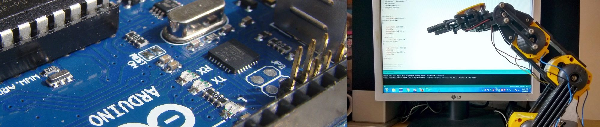
Arduino provides very simple approach for many interfaces. This is a beginner’s tutorial of testing a robotic arm with arduino board and driver IC. As arduino itself cannot deliver the required current to motors a driver is required. The robotic arm in this experiment uses DC gear motors that can be easily drive using the well-known L293D driver. L293D is basically a quadruple half-H driver. Therefore one can drive two dc motors with a single L293D. we need to reverse the direction of the motor this is another reason for using L293D. Otherwise where direction reversal is not required we can use a single MOSFET as a driver.
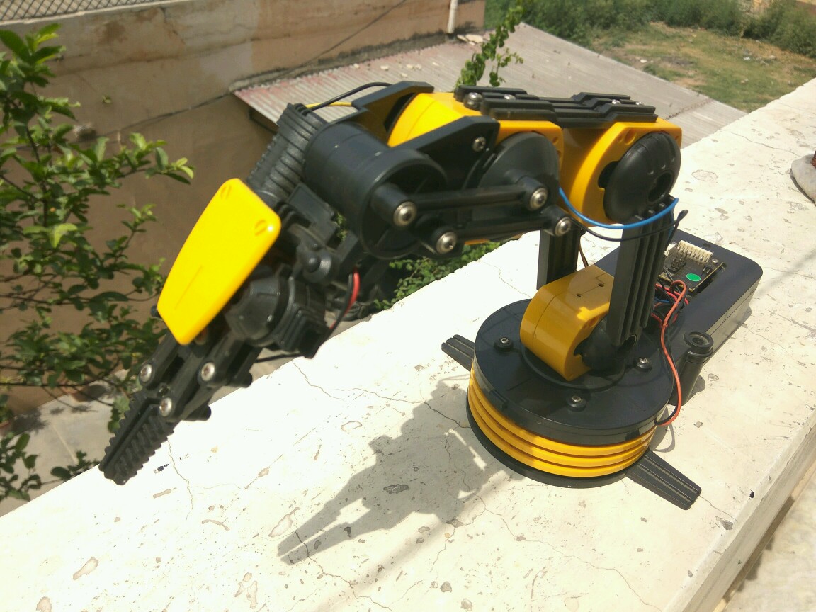
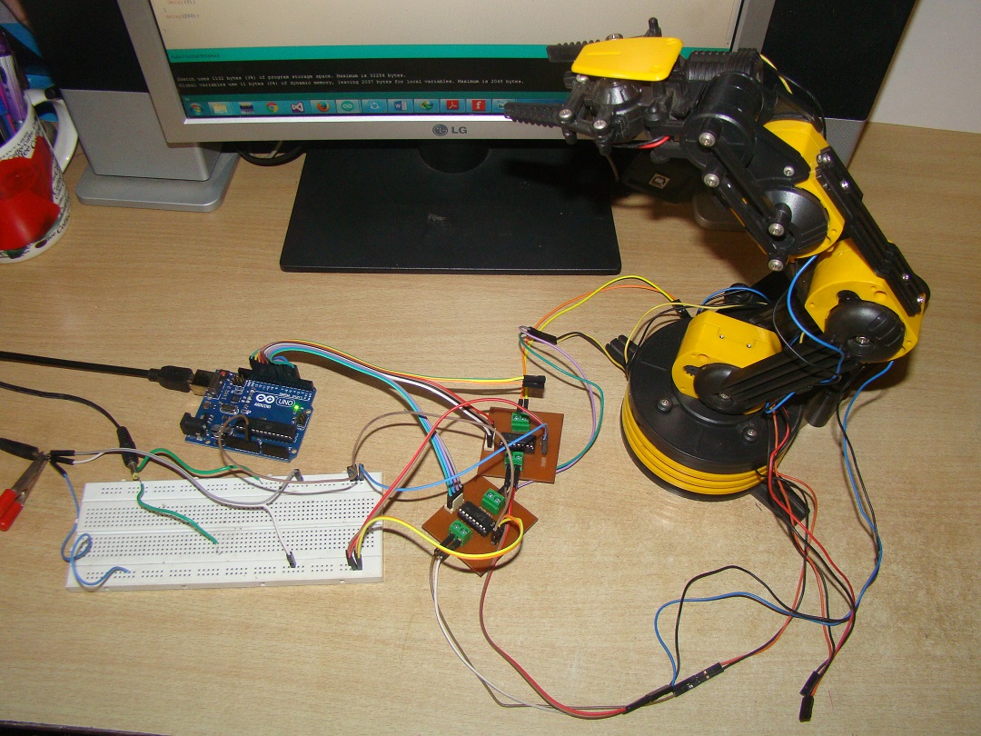
Robotic Arm
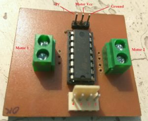
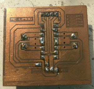
L293D Board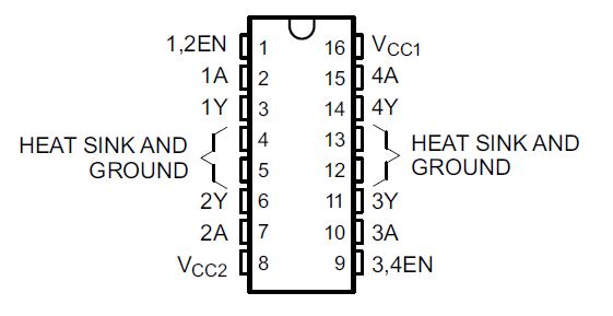
Note:
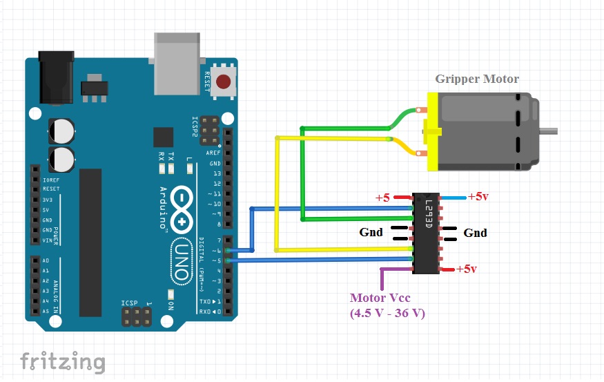
Use separate Supply for L293D
Avoid using supply from Arduino Board. Arduino can be powered by USB or a dc adapter can be used.
Common Arduino and L293D ground pins.
L293D can deliver maximum of 600mA of current. This is suitable for motors in this robotic arm.
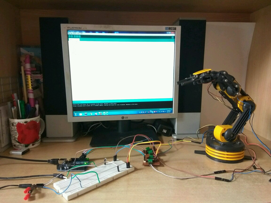
Setup
The code is written to test the motor of gripper. Although the robotic arm in this setup has five motors. Code for other motors can be written in same way. As there are no encoders or sensors for reading the position of the motor, a pulse is generated instead of making the control pin directly high . This slow downs the speed of the motor. Arduino sketch is given below. All other motors can be tested in same manner.
#define in5  5
#define in6  6
int i;
void setup() {
  pinMode(in5, OUTPUT);
  pinMode(in6, OUTPUT);
}

void loop() {
  digitalWrite(in5, LOW);
  for (i = 0; i <= 100; i++)
  {

    digitalWrite(in6, HIGH );
    delay(3);
    digitalWrite(in6, LOW );
    delay(3);
  }
  delay(200);

 digitalWrite(in6, LOW);

 for (i = 0; i <= 100; i++)  {
    digitalWrite(in5, HIGH );
    delay(3);
    digitalWrite(in5, LOW );
    delay(3);
  }
  delay(200);

}